UnaShield Hardware Guide
Version v1.0
Contents
About the UnaShield
Schematics
Pin Assignment
Features and Functions
Frequently Asked Questions
About the UnaShield
 UnaShield is an Arduino Shield with a Sigfox transceiver module that is compatible with Arduino Uno R3 and other Arduino-based development boards. It uses Sigfox-certified WISOL or Radiocrafts modules to support all RCZs (Radio Configuration Zones).
-
RCZ1: Europe, Iran, Oman, South Africa
-
RCZ2: Brazil, Mexico, USA
-
RCZ3: Japan
-
RCZ4: Argentina, Australia, Colombia, Hong Kong, Malaysia, New Zealand, Singapore, Taiwan, Thailand
| Features | V1A (20161128) | V2 (20170325) | V2S (20170107) | V2S (20170325) | V2S2 (20181109) | |
|---|---|---|---|---|---|---|
| Sigfox Module | Radiocrafts RC1692HP-SIG | ✔ | ||||
| WISOL WSSFM10R | ✔ | ✔ | ✔ | ✔ | ||
| Sigfox RCZ | 2 / 4 | 1 / 2 / 3 / 4 | 1 / 2 / 3 / 4 | 1 / 2 / 3 / 4 | 1 / 2 / 3 / 4 | |
| Sensor | Accelerometer (MMA8451Q) | ✔ | ✔ | |||
| Accelerometer (LSM303AGR) | ✔ | |||||
| Temperature Sensor (BME280) | ✔ | ✔ | ✔ | |||
| Humidity Sensor (BME280) | ✔ | ✔ | ✔ | |||
| Pressure Sensor (BME280) | ✔ | ✔ | ✔ | |||
| Push Button | ✔ | ✔ | ✔ | ✔ | ||
| Peripheral Connection | Digital Grove (I2C) | ✔ | ✔ | ✔ | ✔ | |
| Analog Grove | ✔ | ✔ | ✔ | ✔ | ||
| LED | Power Indication | ✔ | ✔ | ✔ | ✔ | ✔ |
| General Indication | ✔ | ✔ | ✔ | ✔ | ||
| Module Status Monitor | ✔ | ✔ | ✔ | ✔ | ||
| Antenna | Matching Circuit | ✔ | ✔ | ✔ |
Schematics
(Click the image to enlarge)

【UnaShield V1A】

【UnaShield V2S】20170107

【UnaShield V2 / V2S】20170325

【UnaShield V2S2】20181109
Pin Assignment
| Arduino Pins | UnaShield V1A | UnaShield V2 / V2S / V2S2 | Description |
|---|---|---|---|
| Reserved | NC | NC | Reserved |
| IOREF | 5V | 5V | 5V Power Source from Arduino platform |
| RESET | RESET | RESET | Reset Arduino MCU & Sigfox Module;Low active |
| 3V3 | 3V3 | 3V3 | 3V3 Power Source from Arduino platform |
| 5V | 5V | 5V | 5V Power Source from Arduino platform |
| GND | GND | GND | Grounding & power/signal reference level |
| GND | GND | GND | Grounding & power/signal reference level |
| VIN | NC | NC | Extra power source input of Arduino platform |
| A0 | NC | NC | Analog Pin-0 |
| A1 | NC | NC | Analog Pin-1 |
| A2 | NC | A2 | Analog Pin-2;Grove Connector #2 |
| A3 | NC | A3 | Analog Pin-3;Grove Connector #2 |
| A4 | NC | I2C-SDA | Analog Pin-4;Grove Connector #1 |
| A5 | NC | I2C-SCL | Analog Pin-5;Grove Connector #1 |
| SCL | NC | NC | Branch of A5 (I2C-SCL) |
| SDA | NC | NC | Branch of A4 (I2C-SDA) |
| AREF | NC | NC | Reference level input for Arduino MCU |
| GND | GND | GND | Grounding & power/signal reference level |
| D13 | NC | NC | Digital Pin-13 |
| D12 | NC | NC | Digital Pin-12 |
| D11 | NC | NC | Digital Pin-11 |
| D10 | NC | NC | Digital Pin-10 |
| D9 | NC | Red-LED | User Programmable Red LED |
| D8 | NC | Green-LED | User Programmable Green LED |
| D7 | NC | Wakeup | Wakeup onboard module from deep sleep mode |
| D6 | NC | Button | Push button;Push to low signal level |
| D5 | UART-RX | UART-RX | UART receiving pin |
| D4 | UART-TX | UART-TX | UART transmitting pin |
| D3 | NC | INT2 | Interrupt#2 of Accelerometer INT2 (V2S2: Select by J205) |
| D2 | NC | INT1 | Interrupt#1 of Accelerometer INT1 |
| D1 | NC | NC | Digital Pin-1 |
| D0 | NC | NC | Digital Pin-0 |

- The five pins marked by
*are required for proper operation of the onboard Sigfox module. Even though UnaShield is designed for Arduino Uno R3, the UnaShield can be integrated with another device as a Sigfox network adapter if these essential five pins are properly connected.
- The onboard Sigfox module works with DC 3V3 power. All the Arduino pins used by the UnaShield are connected to a level-shifter to ensure that the pin voltage is always fixed at 3V3.
Features and Functions
1. SMA Connector
The SMA (SubMiniature version A) Connector is used for connecting the provided coaxial RF antenna to the UnaShield.
To prevent damage to the onboard Sigfox module, always connect the antenna before powering up the UnaShield and before sending any Sigfox messages.
2. Sigfox Module
UnaShield V1(A) embeds a Radiocrafts Sigfox module RC1692HP-SIG, certified for RCZ2 and RCZ4; UnaShield V2 / V2S uses a WISOL Sigfox module in the WSSFM10R Series, certified for all four RCZs. The Sigfox modules may be controlled via the UART interface with serial terminal commands (similar to the AT Command Format used by modems).
| UnaShield V1A | UnaShield V2 / V2S / V2S2 |
|---|---|
| Radiocrafts RC1692HP-SIG | WISOL WSSFM10R |
| For RCZ2 and 4 | For all RCZs: RCZ1, 2, 3 and 4 |
3. Arduino Uno Standard Header

UnaShield has four Arduino standard headers (pin connectors): one 6-pin header, two 8-pin headers, and one 10-pin header. Not all Arduino pins are used by the UnaShield, some Arduino pins are passed through unmodified by UnaShield.
You may use the unused Arduino pins to connect other sensors and components. However take note that the voltage level of Arduino Uno R3 is 5V, which may not be directly usable by some sensors or components.
For the details of each Arduino Uno pin assignment and definition, please check the Arduino official website:
https://www.arduino.cc/en/Main/ArduinoBoardUno
4. Push Button (UnaShield V2 / V2S / V2S2 only)
A Push Button (tact switch) is connected to the D6 Digital Input pin of the Arduino Uno.
The button may be programmed in Arduino sketches to trigger certain functions when pressed.
5. Grove Connector (UnaShield V2 / V2S / V2S2 only)
UnaShield V2S is equipped with two Grove Connectors, a standard 4-pin connector for Grove sensors. You may connect sensors or components with Grove interfaces to extend the capabilities of the Arduino device.
Grove Connector #1:Connected to Arduino I2C Digital Interface (SCL and SDA)
Grove Connector #2:Connected to Arduino Analog Input/Output interface (A2 and A3)
- Note: Due to hardware design, UnaShield V2/V2S A2 and A3 pin cannot work as analog read pin.
The onboard Grove connectors support two voltage levels: 3V3 or 5V. Select the Grove voltage through jumper J204.
| Floating | 5V | 3.3V (Default) | |
|---|---|---|---|
| Jumper J204 | 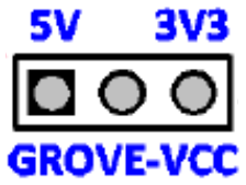 |
 |
 |
6. LED Indicator and Manual Switches (UnaShield V2 / V2S only)
Eight onboard LEDs are used to show the status of the UnaShield. The LEDs may be disabled through the jumpers J201, J202 and J203.
Jumper J201 – Controls the Status LEDs of the WISOL module (TX, RX, CPU & RF)
| Disabled | Enabled (Default) | |
|---|---|---|
| Jumper J201 |  |
 |
Jumper J202 – Controls the Grove Voltage Level LED (3V3 or 5V)
| Disabled | Enabled (Default) | |
|---|---|---|
| Jumper J202 | |
|
Jumper J203 – Controls the User-Programmable LEDs (D8, D9)
| Disabled | Enabled (Default) | |
|---|---|---|
| Jumper J203 | |
|
7. I2C Interface (UnaShield V2 / V2S only)
I2C (Inter-Integrated Circuit) is a two-wire, bidirectional protocol for connecting multiple sensors and components on the same pair of wires.
The I2C interface requires two pins: data line (SDA) and clock line (SCK). I2C works in the daisy-chain configuration, so one master device can communicate with more than one slave device, just by selecting the unique I2C address of the slave device.
The UnaShield accelerometer sensor and temperature / humidity / pressure sensor are connected to the I2C bus by unique I2C addresses, which are preset in the sensor hardware.
NXP Accelerometer (G-Sensor) – MMA8451Q
| SA0 | I2C Address | Default |
|---|---|---|
| LOW | 0x1C | ✔ |
| HIGH | 0x1D |
ST Accelerometer (G-Sensor) – LSM303AGR
| Function | I2C Address | Default |
|---|---|---|
| Accelerometer | 0x32 | ✔ |
| Magnet | 0x3C | ✔ |
BOSCH Temperature / Humidity / Pressure Sensor – BME280
| SD0 | I2C Address | Default |
|---|---|---|
| LOW | 0x76 | ✔ |
| HIGH | 0x77 |
Grove Connector #1
Grove Connector #1 is also connected to the I2C bus. The sensor or component connected through Grove Connector #1 must use an I2C address that is distinct from the above I2C addresses, to avoid address conflict.
8. INT selector (UnaShield V2S2 only)
Select UnaShield V2S2 onboard G-Sensor interrupt signal from accelerometer interrupt 2 or magnet sensor interrupt.
Jumper J205 - Select onboard G-Sensor Interrupt signal.
| Jumper | Floating | Magnet Interrupt | Accelerometer Interrupt |
|---|---|---|---|
| J205 |  |
 |
 |
Frequently Asked Questions
Can the UnaShield be used on all Arduino boards?
UnaShield has been thoroughly tested on Arduino Uno R3. However it’s not compatible with all variants of Arduino boards, due to the different pin definitions. Here two classes of Arduino boards that are incompatible with the UnaShield due to the pin definitions:
Arduino Mega / Mega2560: Only the following pins are supported for UART RX in Mega & Mega2560:
- 10, 11, 12, 13, 50, 51, 52, 53, 62, 63, 64, 65, 66, 67, 68, 69
Arduino Leonardo / Micro: Only the following pins are supported for UART RX in Leonardo & Micro:
- 8, 9, 10, 11, 14, 15, 16
If you are using one of these Arduino boards, perform the two steps below to switch the UnaShield’s UART Receiving Pin (UART-RX) from Arduino D5 Pin to another Arduino pin with UART RX capability.
Note that Arduino D5, D6 Pins are High Impedence (HI-Z). The replacement pins should also be HI-Z pins, as indicated in the table below.
Step 1
Assign the original UnaShield Pin 5 (UART-RX) as an input, by choosing a setting marked Green in the table below. You may keep UnaShield Pin 5 (UART-RX) disconnected on the Arduino Uno R3.
Step 2
Connect UnaShield Pin 5 (UART-RX) to one of the Arduino pins below with UART receiving capability, so that it becomes the new UART-RX. Use a jumper cable to connect the pins.
| DDxn | PORTxn | PUD (in MCUCR) | I/O | Pull-Up | Comment |
|---|---|---|---|---|---|
| 0 | 0 | X | INPUT | NO | HI-Z |
| 0 | 1 | 0 | INPUT | YES | |
| 0 | 1 | 1 | INPUT | NO | HI-Z |
| 1 | 0 | X | OUTPUT | NO | Output Low |
| 1 | 1 | X | OUTPUT | NO | Output High |
Can UnaShield work as a breakout board?
UnaShield can be the breakout board of the onboard Sigfox module. Only five pins need to connected, so that the Sigfox module can be controlled by any external MCU (e.g. ARM CPU, Raspberry Pi) or integrated to any existing system.
| Power Pins: | UART Interface: |
|---|---|
| - 3V3 | - UART-TX (D4) |
| - 5V | - UART-RX (D5) |
| - GND |
Both 3V3 and 5V UART signaling levels are accepted. The UnaShield’s level-shifting circuit regulates the 5V UART signaling to 3V3, which is the nominal power level of the onboard Sigfox module.
Can the UART Interface be reused?
The Arduino D4, D5 pins are used by the UART interface on UnaShield, for communicating with the onboard Sigfox module.
UART communications is designed for two endpoints only, so D4, D5 cannot be connected for any other purpose.
Can the I2C Interface be reused?
The Arduino A4, A5 pins are used by the I2C interface on UnaShield, connected to he UnaShield accelerometer sensor, temperature / humidity / pressure sensor and Grove Connector #1.
The I2C interface works in daisy-chain mode. Each terminal should have a unique I2C address so that they may be connected serially. Every message transmitted on I2C contains the unique I2C address of the receiver, so that only one of the terminals in the daisy-chain can intercept and process the message.
Any I2C device with a unique and distinguishable address can connect to these two pins simultaneously.
Can Grove Connector #2 (A2, A3) be reused?
The A2, A3 pins are connected to Grove Connector #2 and to Grove sensor connected to that port. If Grove Connector #2 is not connected to any Grove sensor, then A2, A3 can be used for other Analog Input/Output connections.
Can Arduino Pins D8, D9 be reused?
The D8 & D9 pins control the User-Programmable LED. Remove jumper J203 to disable the LED function, then D8, D9 may be reused for other Digital Input/Output connections.
What’s the guideline for deciding if a pin is reusable?
Each pin can only be assigned to one function. The pin may not be reused until the default function of that pin has been deactivated. If the same pin is used by two circuits (e.g. UART Interface and Digital Input/Output), the conflict in the electrical signalling will lead to failure of both functions.
The only exception is the I2C connection, which supports daisy-chaining of multiple sensors on the same two I2C pins.
What are the limitations of the Arduino Input/Output pins?
UnaShield was designed for the Arduino hardware platform. All the Arduino Input/Output pins derive from the Arduino MCU. Maximal current for each I/O pin is 40mA on Arduino Uno R3.
How do I activate the UnaShield?
Follow the steps here to activate your UnaShield:
Each UnaShield activated will enjoy one year of free Sigfox subscription.
What is the warranty for UnaShield?
The UnaShield is covered by a 3-month warranty, one-for-one exchange. Proof of purchase must be produced upon exchange.
UnaShield Developer’s Guide
The UnaShield Arduino library and sample codes for the may be downloaded at
Getting the UnaShield
To order the UnaShield, please contact UnaBiz:
Singapore
Ms. Kimberley Thong
Business Development Manager
Kimberley.thong@unabiz.com
Taiwan and Rest of the World
Mr. Nicolas Baele
Global Account Manager
Nicolas.baele@unabiz.com